Simulating a check valve with a WDLANG module
SIC does not include any device or regulation module of the “check valve” type, a device that only allows the discharge to flow in one direction. To model this type of device, you must program a regulation module yourself. This is what this tutorial proposes to do using the WDLANG module.
Creation of the module and connection to the devices
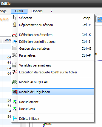
In hydraulic mode, go to the tools menu > Regulation module
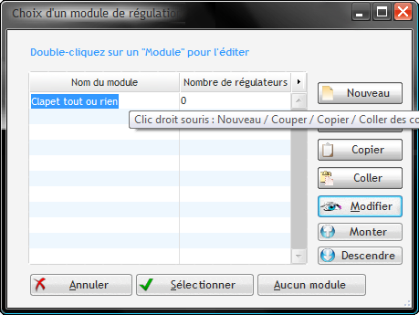
In the window that opens, click on « New », give a name to the module, then click on « Modify »:
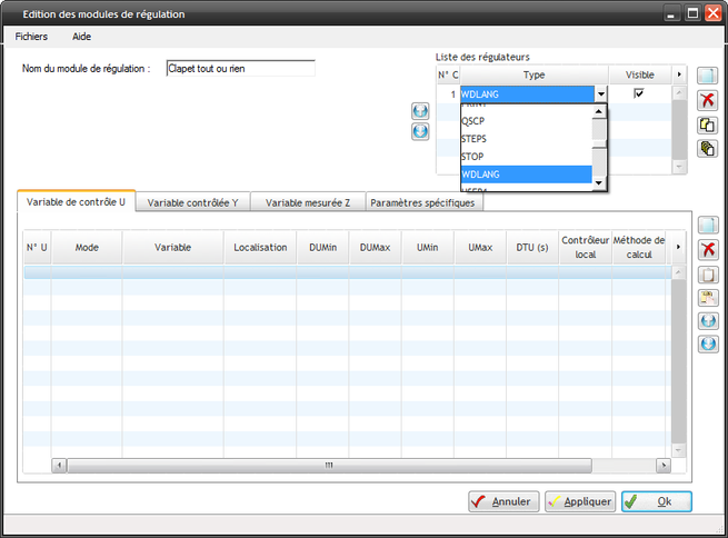
In the regulation modules editing window, add a WDLANG regulator by choosing in the drop-down list at the top right:
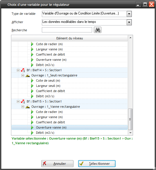
Add a control variable U by clicking on the first row of the table and choose the opening of a gate where the check valve must be placed:
Define the parameters of the control variable: for a check valve, you must use an absolute mode command (i.e. the value sent by U will be equal to the value of the opening) and you can optionally define Umin and Umax so that they correspond to the minimum and maximum opening of the gate in case the regulation algorithm would return values outside the range. Then, we must define the hydraulic measurements that will allow us to command the check valve. I suggest putting the upstream water elevation in the controlled variable (Y) and the downstream water elevation in the measured variable (Z).
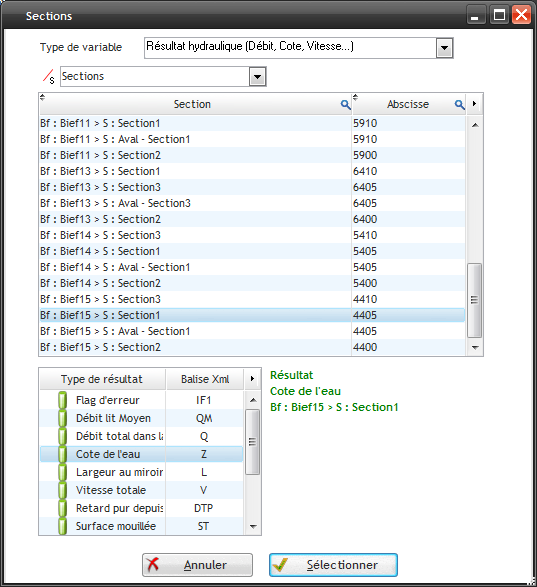
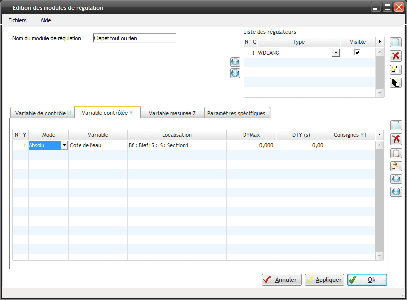
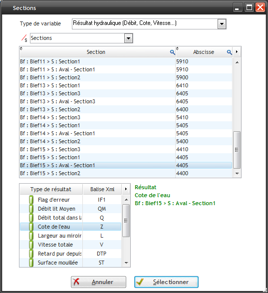
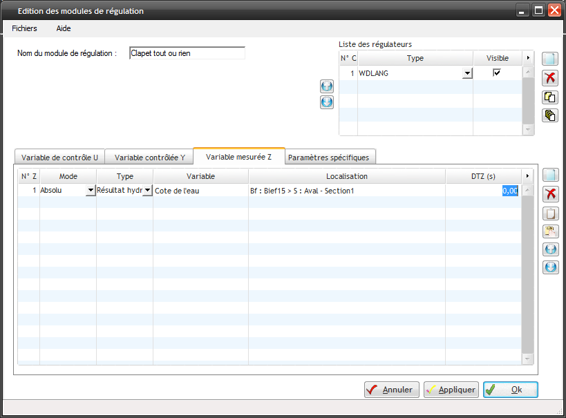
I set Y and Z to absolute in order to be able to compare the water elevations Z of the two sections.
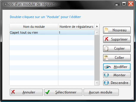
Click on « Select ».
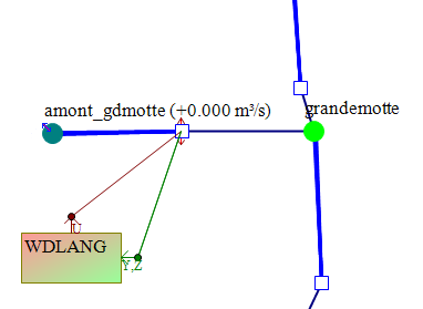
On the network chart, a « WDLANG » box must be connected to the gate:
Writing the regulation script
Then, we can launch SIRENE and we will be able to write the regulation script during the simulation.
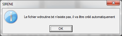
At the launch of SIRENE, a window opens with a first message:
We can write our code in the WDLANG module window:
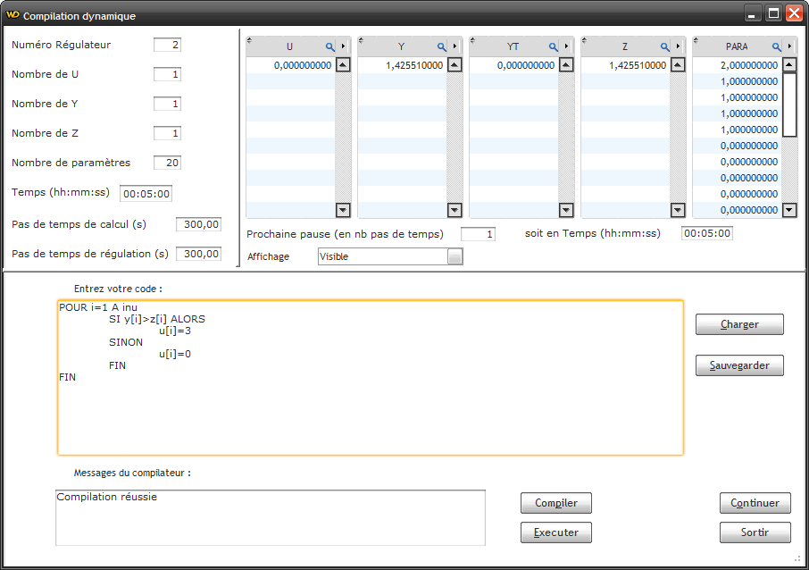
In the U, Y and Z tables, we see in real time respectively, the opening, the upstream water elevation and the downstream water elevation of the gate.
The portion of code in WDLangage above loops over all the U and, for each U, will open the gate to 3 meters if the upstream water elevation is greater than the downstream water elevation and close the gate otherwise. In this way, we can add other check valves by adding lines in the U, Y and Z of the regulation modules editing window.
The script must be saved and compiled with the buttons ad hoc. Then, if we click on Run, the script will update the value of U.
If we click on Continue, it will run the simulation until the time defined by the “Next pause (in number of time steps)” field.
Simulation parameters and results
Here is an example where we can see the check valve working:
Opening of the gate: 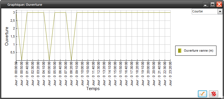
Upstream water elevation of the check valve: 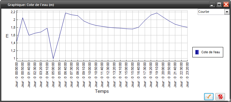
Downstream water elevation of the check valve: 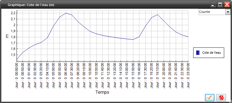
We note that the sudden change of opening of the gate creates numerical instabilities. The calculation must be done in nonlinear mode by putting 1 in “Frequency for computing the derivative (Quasi-Newton)” of the unsteady flow calculation parameters: 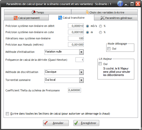
Another point to note is that the opening command of the check valve is carried out with one time step of delay on the measurements. That is to say that the check valve closes if at the previous time step the discharge started to flow in the reverse direction, and does not reopen until the upstream water elevation is greater than the downstream water elevation at the previous time step. It is therefore necessary, if the opening/closing frequency of the check valve is high, to possibly decrease the calculation time step.