 Description of the offtakes
Access to the description of an offtake by double-clicking a node in the graph or in the tree view.

From SIC 5.20, intermediate nodes can have multiple offtakes.
Characteristics of an offtake
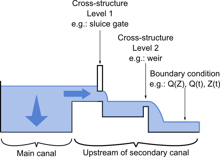
Each offtake has the following characteristics:
- A downstream boundary condition which can be an imposed flow $Q(t)$, a fixed elevation $Z(t)$, a rating curve $Q(Z)$ (or rather $Z(Q)$ ), or a law function $Q=Z^{\alpha}$ (or rather $Q(t)=Q_{ref} [(Z(t)-Z_{0})/(Z_{ref}-Z_{0})]^{\alpha}$ to be more precise)
- Optionally a first level of structure with one or more devices including one may be regulated in order to obtain a discharge goal.
- Possibly a second level of structure downstream of the first containing one or more fixed devices.
Regulate an offtake for obtaining a targeted discharge
In steady (FLUVIA) and unsteady (SIRENE) calculation, it is possible to calculate a characteristic of a device (opening of a gate, sill of a weir...) situated in the first level of structure to obtain a defined discharge (called "targeted discharge" or maybe sometimes also "objective discharge") at the offtake.
Initial discharge
The initial discharges serves two purposes :
- The initial discharge at the offtakes is used to calculate the distribution of the discharge in the reaches of the network for the steady calculation (See Verification of initial rates).
- When an offtake is not in regulation "targeted discharge" mode, the discharge calculation is performed by dichotomy and requires an initial discharge to start the calculation.
Reference discharge
The reference discharge is not directly used in hydraulic calculations. In EdiSIC result mode, it is used to calculate indices of performance by comparing the distribution (calculated discharge) and the request (reference discharge).
The reference discharge can also be used as an input by the regulation modules.
Sign convention for discharge
Since the discharges can enter or leave the hydraulic system (at nodes or at sections through lateral discharges or seepage), a sign convention had to be choosen. All discharges entering into the hydraulic system are positive. All discharges leaving the hydraulic system are negative. This is true at all nodes and cross sections for lateral discharges at the data input stage and also at the result display stage. For cross structures (gates, weirs, etc) the sign convention is positive for flows from upstream to downstream and negative for downstream to upstream flow directions.