The ATVPID method
The ATVPID method consists in running the ATV method, and then apply the PID and then move on to the next device and do the same thing so on all the devices selected for this method ATVPID (if we have therefore several U).
To understand this method it is advisable to read the documentation of the ATV method and on the PID method. A paper details these procedures: https://hal.archives-ouvertes.fr/hal-00450874/document.

For the ATVPID method we read 8 parameters under the format (7(F8.2,1X),F8.2):
*         R     METH    CYCLE     UouZ    CHOIX  AntiWup       MG       MP

PS= 0.20 8.00 3.00 1.00 2.00 1.00 10.00 61.00 - $R$ is the switch value (by default it is the same for all U if you have several, but can be changed with ATVPID.TXT, cf below). It is positive for the classical feedback counter-reaction (e.g. downstream control) and negative for inverse configuration (e.g. upstream control).
- METH is the method used to calculate the P, PI and PID coefficients ATV:
- 1 = Astrom p. 137 Table 4.2
- 2 = Astrom p.141-142 (r=0.5, Phi = 20°)
- 3 = Astrom p.141-142 (r=0.41, Phi = 61°)
- 4 = Astrom p.141-142 (r=0.29, Phi = 46°)
- 5 = Flaus p. 72, Table 2.7
- 6 = Flaus p. 72, Table 2.8 slight overshot
- 7 = Flaus p. 72, Table 2.8 without overshot
- 8 = Cemagref from gain and phase margins
- CYCLE is the number of cycles you want (or manual validation if = 0)
- UouZ allows (si =1) to use the measure Z instead of the control action U to compute Ku (this is usefull in case you have a saturation of the U, or if you have a limited precision of the actuators and that you are using real data using the SCADA link). In this case you define the corresponding Z as the measure of the gate opening, and this way you will get the real applied gate opening instead of the theoretical one.
- CHOIX corresponds to the type of controller we activate when ATV has found the correct coefficients: P (CHOIX=1), PI (CHOIX=2) or PID (CHOIX=3).
- AntiWup is the Antiwindup option as defined for the PID controller (cf. routine CPID).
- MG is the desired Gain Margin (for option 8)
- MP is the desired Phase Margin (for option 8)
As can be understood from a reading of the above parameters to provide, the $R$ relay, by default, is the same for all the control variables U. This is restrictive because there are many cases where it is desired to have different values, for example when tuning automatically in cascade flow controllers and gate opening controllers, or with upstream controllers for certain structures and downstream controllers for the others. Since the release of version 4.29g this is possible by creating a ATVPID.TXT file in the subdirectory of the current data. This file must contain a priori as many lines as U of variables, each line indicating the desired value of the variable relay for the corresponding U. These lines correspond to the U in the same order as shown in the list of the control action variables. If lines are missing or do not correspond to a real value, then the default value from $R$ parameter above will be used.
This file also allows adding timers, ie a time (in seconds) to wait before triggering the next ATV on the following U (all of course in case there are several U).
Example of ATVPID.TXT file:
*

*

*

*

0.5

3600.

3600.

3600.

3600.

3600.
The second value of the relay (for U(2)) will be the one from the reg file because the line contains a "*" character, which is therefore not a real acceptable value. The relay of the first variable U is -0.11, -0.22 for the third variable, the variable -0.12 fourth and fifth variable +0.33.
The values of the relay for U(1) to U(4) are those from the above parameters $R=0.2$ since the line contains a "*" character, which is therefore not a real acceptable value. Relay for the fifth variable U(5) will be 0.5.
The temporizations of 1h = 3600s are added, ie that the ATVPID regulation module will wait 1h before launching the next ATV on the variable U that follows.
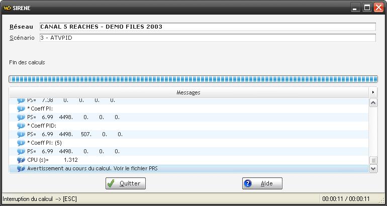
When running the transient calculation with this module, the results obtained and the corresponding PID coefficients are displayed on the screen in the normal message window (see below), and also on a ATVPIDCOEF.TXT file. The example provided with SIC (ex2) gives, for example:
| 1.70 | 3598.78 | 0.00 | 0.00 | 0.00 | 2400.00 | 4.59 | 1200.00 | 19.78 |
| 2.42 | 3598.78 | 0.00 | 0.00 | 0.00 | 2400.00 | 6.54 | 1200.00 | 31.30 |
| 3.85 | 3598.78 | 0.00 | 0.00 | 0.00 | 2400.00 | 10.41 | 1200.00 | 35.26 |
| 3.01 | 3598.78 | 0.00 | 0.00 | 0.00 | 2400.00 | 8.13 | 1200.00 | 29.83 |
| 6.99 | 4498.48 | 0.00 | 0.00 | 0.00 | 3000.00 | 18.91 | 0.00 | 0.00 |
The columns correspond, respectively to: $K_p$, $T_i$, $T_d$, $N$ (filter), Antiwindup (0 if not actif or 1 if actif), $T_u$, $K_u$, $\widetilde{T_u}$ $\widetilde{K_u}$ (for the report downstream-upstream, cf bibliographical references bellow for the details of the équations)